Capacitors
At this point, I have assumed that you have read the section on resistors and sand filters. Explaining a capacitor in terms of this analogy with a flow of water is more difficult; however, we will look at associating the capacitor with an unstretched membrane blocking the flow of water as is shown in Figure 1.
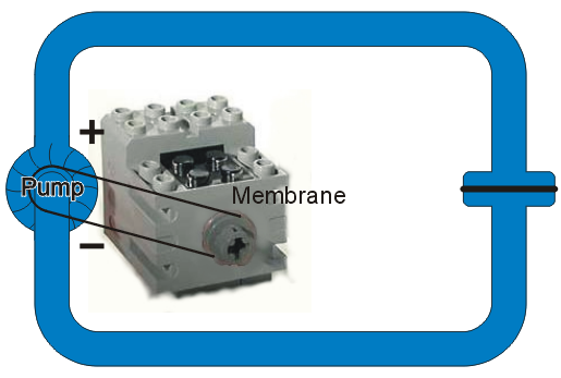
Figure 1. A pump in a closed loop with a membrane blocking the flow.
Suppose we turn on the pump. We now have a force which begins to move the water and consequently the membrane starts to stretch as is shown in Figure 2. Because the membrane is unstretched, there is no force on it and it begins to bulge; however, soon the membrane stretches until the force from the pump equals the force pushed back by the stretched membrane. At this point, the initial water flow stops again.
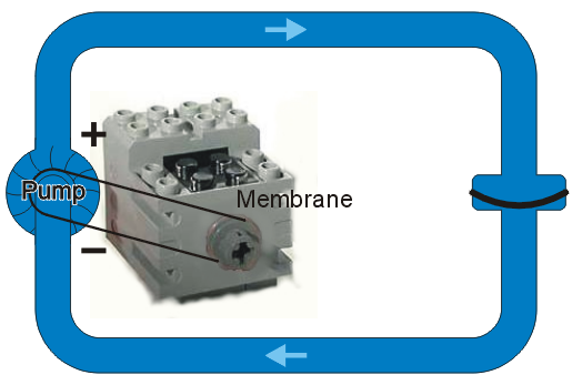
Figure 2. The membrane stretched to the point of equaling the force of the motor.
A Sand Filter in Parallel
Next, let us put a resistor in parallel with the membrane. If the membrane is initially unstretched and the pump is turned on, the membrane will offer no resistance and thus we will have the situation where no water passes through the sand filter; however, after the membrane becomes stretched to the point where the force it pushes back with equals the force from the pump, all water flow will then be through the sand filter.
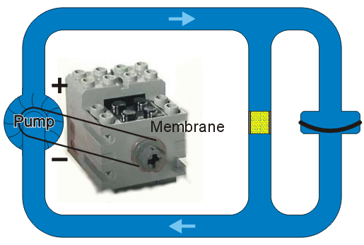
Figure 3. A membrane in parallel with a sand filter.
Suppose we include a valve which blocks the water flowing from the pump as is shown in Figure 4. With the valve open, the membrane stretches until the force from the membrane equals the force of the pump.
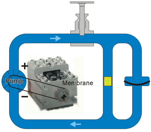
Figure 4. The addition of a valve to the circuit of water.
When the valve is closed, the force on the membrane is now removed and it now pushes back with the same force as the pump originally pushed, as is shown in Figure 5.
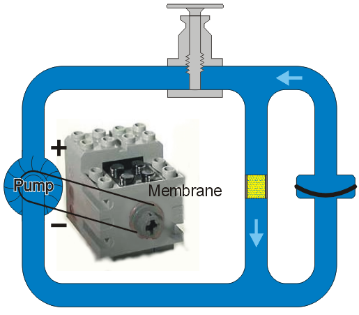
Figure 5. Closing the valve with a sand filter in parallel with the membrane.
Once the membrane has returned to its natural position, the circulation ceases as is shown in Figure 6.
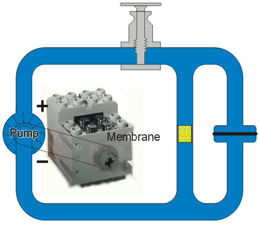
Figure 6. The flow ceasing once the membrane returns to its neutral state.
An interesting question is what does the water flow look like after the valve closes? Initially, the flow is unchanged: the force from the membrane equaled the force from the pump. However, as the membrane returns to its original position, it exerts less and less force on the water and so therefore the water flow decreases slowly. The actual decrease in flow is exponential, but this is the subject of a course in physics.
A Sand Filter in Series with the Membrane
Suppose we start with Figure 1 but put a sand filter in series with the membrane as is shown in Figure 7. What difference should this make?
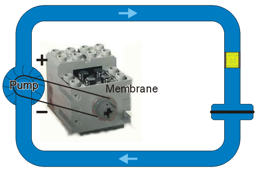
Figure 7. A sand filter in series with the membrane.
Because the sand filter is already slowing down the flow of water, it would make sense that by adding the sand filter in series, it would take longer for the membrane to be stretched to its maximum capacity. As the membrane is stretching, the flow of the water is decreasing and therefore the resistance from the sand filter becomes negligible until there is no flow and the force from the membrane equals the force of the pump. Only, it will take more time.
A Source with a Constant Current
Suppose, as with the model of the resistor, we have an engine which we can control to ensure that the flow of water remains constant. In this case, as you may guess by inspecting Figure 8, the membrane will begin to stretch and ultimately it will rupture.
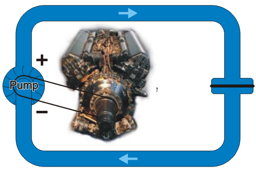
Figure 8. Using a motor which is able to provide a constant current.
Similarly, a capacitor will fail if placed in series with a current source. This analogy breaks down at this point, as when the membrane fails in this example, the water would begin to flow freely. When a capacitor is overloaded, it tends to burn out and it stops all flow.
Isn't This a Small "Capacity"
You may notice that the membranes in the previous figures are not very large—only a very small volume of water could be stored by them. Electric capacitors, however, hold significantly more charge. To demonstrate how this is done, consider a stretching the radius of the pipe along a small section and a semi-rigid membrane is made to fit in the centre of this disk as is shown in Figure 9.
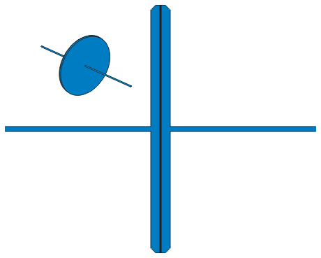
Figure 9. A model of a high-capacity membrane.
Now, when a current flows under pressure down the pipe leading into the membrane, as is shown in Figure 10, there is a significantly larger region for displacement and therefore the membrane has a much larger capacity. Also, the current on the other side of the membrane must exactly equal the current coming into the membrane.
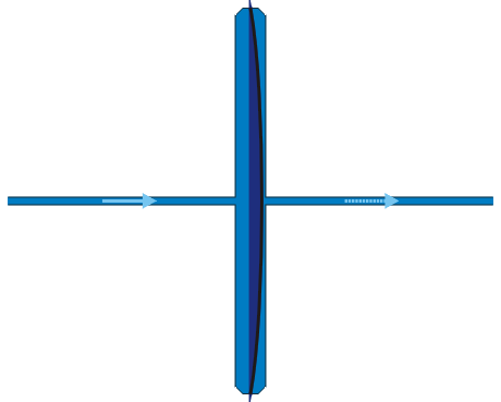
Figure 10. The stretch of the membrane under a forced current
together with the resultant flow on the other side.
If the pressure is removed, the membrane will now provide pressure in the oppose direction causing the flow to reverse as is shown in Figure 11.
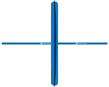
Figure 11. The reverse flow once a filled membrane has the
pressure removed.
Department of Electrical and Computer Engineering
University of Waterloo
200 University Avenue West
Waterloo, Ontario, Canada N2L 3G1
Website maintained by Douglas Wilhelm Harder