Universal Asynchronous Receiver/Transmitter (UART)
Under construction...
This page has four main topics:
- background
- using the UART on the Keil board,
- listening to the UART in the simulator,
- listening to the COM port on your computer, and
- troubleshooting.
1. Background: the universal asynchronous receiver/transmitter (UART)
In Project 1, you communicated with the LCD screen. Another means of communication is through the universal asynchronous receiver/transmitter (UART). This is used for serial communication; that is, one bit at a time. The transmitter will break one more more bytes of data into individual bits, send the bits over the connection, and the receiver will reassemble these into a sequence bytes. You may contrast this with parallel communication where multiple bits are sent at a time.
For synchronous communication (such as on a bus), both the transmitter and the receiver must share a common clock. Parallel communications, such as between a processor and either printers or hard-disk drives, are often synchronous: entire words are sent simultaneously and a separate wire is used to transmit the clock pulses.
The asynchronous component of the name indicates that there is no common clock signal between the two systems. Instead, both the sender and receiver are configured to use approximately the same clock rate and the sender flags that it is going to send a byte by sending a start bit (low). During this time, the receiver is sampling the signal at approximately eight (8) times per clock cycle. If the duration of the start bit is at least half a cycle long, it is assumed to signal the start of a byte and the first low sample is taken to be the first sample of the start bit; otherwise, it low is interpreted as noise. Without any knowledge of what the receiver is doing, the as soon as the start bit is sent, the next eight cycles send the eight bits of the byte from least to most significant bits followed by one more more stop bits (high). The receiver interprets this information appropriately and converts the bits to a byte. As an example, the signal shown in Figure 1 shows how the byte 001010102 (42 or '*') would be sent and received.
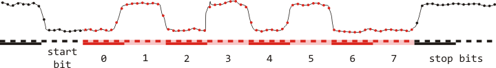
Figure 1. A signal transmitting the byte 001010102
or 4210 or '*'.
Note: the use of high as the no data state is a legacy left over from the era of telegraphy where a line is held at high to demonstrate that neither the transmitter nor the wire is damaged.
The bits are stored in a shift register and this is then presented by the device as a complete signal. For example, assuming there are two starting bits, the above signal would be
0000000000000001111111110000000011111111000000001111111100000000000000000111111111111111
This register would then be read and interpreted in software. We will now discuss how this signal is transmitted to and interpreted by your computer.
The signal will be transmitted through the serial port on the Keil board. This is a 9-pin port
You will note that there are both male and female DE9 connectors on the Keil board. It is common that systems using the RS-232 standard (that is, the one used by the UART) have female connectors on the device, while systems using the CAN (controller area network) standard have male connectors on the device. In Microsoft Windows, serial ports using RS-232 are generally referred to as COM ports, usually numbered as COM1, COM2, COM3, etc.
The 16550 UART implemented on the LPC1768 chip is a component not required in the Cortex-M3 design. Instead, it is a feature offered by the chip manufacturer. This removes the requirement of any client of installing a separate UART circuit on the same board.
The UART is connected to DE9 female serial port on the Keil board. This is usually connected via a serial cable to a DE9 male serial port on a computer; however, these days, it is common to find DE9 to USB cables where a driver will simulate an RS-232 connection.
The speed of the transmission is described by the baud rate (named after Èmile Baudot), in terms of the amount of information sent per second. For serial transmission, the bit rate equals the baud rate; however, in parallel transmissions, the baud rate will be lower than the data rate (if four bytes are being sent with each transmission, the baud rate will be one thirty-second the data transfer rate).
For Projects 2 to 5, you will have the option of using the serial port to transmit and receive information.
2. Using printf in the μVision simulator
In order to view output in the μVision simulator using printf, you must:
- download the three files in the source directory and place them in your project folder, and
- include the two source (.c) files in your project in μVision (right click on the appropriate group in the Project panel and select Add Existing Files to Group 'Group name'....
Now you can use the library in your source code with the appropriate initialization. For example, consider a simple Hello World! program:
#include <lpc17xx.h>
#include <stdio.h>
#include "uart.h"

int main( void ){
	SystemInit();

	printf( "Hello World!" );

	while ( 1 ) {
		// does nothing
	}
}
To simulate the execution of this program on the Keil evaluation board, we will use the debugger. Having built the project (F7), to start or stop the debugger, you have three options:
- Ctrl-F5
- Select Debug→Start/Stop Debug Session
- Select the icon
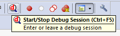
When you do so, a dialog box may appear with the text EVALUATION MODE Running with Code Size Limit: 32K. This indicates that you are using a version of μVision which does not have a full licence; consequently, there are some restrictions including the restriction that the code cannot be larger than 32 KiB—something that should not be an issue for MTE 241. Just select OK.
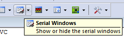
Having started the debug mode, we need to view the output of the UART. To do so, you have two options:
- Select View→Serial Windows→Debug (printf) viewer
- Select the icon
 and then
Debug (printf) Viewer
and then
Debug (printf) Viewer
This opens a tab with the same name in the lower right panel in μVision.
To run the code, you have three options:
- F5
- Select Debug→Run
- Select the icon
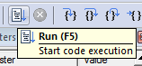
Having done so, you should see
Hello world!
appear in the Debug (printf) Viewer tab.
If your code does not compile, see the troubleshooting section below.
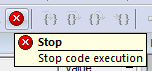
Note: because there is an infinite loop coded into the Hello world program, you can terminate the execution through one of two options:
- Select Debug→Stop
- Select the icon
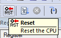
Before you run it again, you should reset the simulation through one of two options:
- Select Debug→Reset
- Select the icon style="vertical-align:middle"
3. Simulating the COM port in the μVision simulator
The next step is to prepare us to work in the UART by simulating a communication in μVision.
To accomplish this, we must give the compiler a recognized directive: Open the options
for the target (Project→Options for Target 'Target name' or select the
magic wand button  ) and select the C/C++ tab. Here,
there is an option to define pre-processor symbols to be recognized by the system. In the
panel for Preprocessor Symbols in the text box marked Define:, enter
__RTGT_UART. This symbol will be defined globally and will be used by the
Retarget.c source file provided.
) and select the C/C++ tab. Here,
there is an option to define pre-processor symbols to be recognized by the system. In the
panel for Preprocessor Symbols in the text box marked Define:, enter
__RTGT_UART. This symbol will be defined globally and will be used by the
Retarget.c source file provided.
Now, load the following source code:
#include <lpc17xx.h>
#include <stdio.h>
#include "uart.h"

int main(void){
	char str_buff[100];

	SystemInit();

	printf( "Enter your name: " );
	scanf( "%s", str_buff );

	printf( "Welcome to MTE 241, %s. :-)", str_buff );

	while( 1 );
}
Build this code and start the simulator (Debug→Start/Stop Debug Session, Ctrl-F5 or
 ) and now select the terminal associated with COM0, unfortunately
named View→Serial Windows→UART #1 or select UART #1 from
) and now select the terminal associated with COM0, unfortunately
named View→Serial Windows→UART #1 or select UART #1 from  .
This opens another tab in the lower right panel with the same name.
.
This opens another tab in the lower right panel with the same name.
This terminal window allows you to both print to the window, but also enter text in the
same window. If you select the UART #1 tab and click in the region, a cursor appears as a
single line. You cannot, at this point, enter text; however, once you select Debug→Run, F5 or
 , because there is call to scanf, it will allow
you to enter text at the terminal.
, because there is call to scanf, it will allow
you to enter text at the terminal.
Enter your name: |
Once you type in your name and hit Enter, the code will continue executing the next statement, and you will see
Enter your name: Douglas Harder
Welcome to MTE 241, Douglas Harder. :-)
When you run the code, the simulator will automatically set the speed of the UART to approximately match your defined baud rate. To view the characteristics of the terminal simulating listening to the UART in the debugger, select Peripherals→UART→UART0. Try changing the baud rate to 1000.
4. Listening the the COM port on your computer
In order to send and receive data from the serial port on a computer, it will be necessary to set up a teletype client, usually referred to as a TTY client, or much more usually, at terminal emulator. The most common is PuTTY, a single executable file that can be downloaded from the PuTTY web site. If it is not available on your computer, you need only download it and copy it to, say, your desktop—no installation is necessary, as it is a self-contained executable which you can execute from where you have saved it. The icon for PuTTY is shown in Figure 2.

Figure 2. The PuTTY icon.
In the laboratory, PuTTY is installed; however, the easiest way to find it is to do a search for PuTTY in the Windows Start menu in the Search programs and files text box.
Having launched PuTTY, you are presented with the PuTTY Configuration dialog. Under session, select a Connection type of Serial and set the speed to the baud rate you have defined in your source file (in the example above, 9600). The changes are shown in Figure 7.
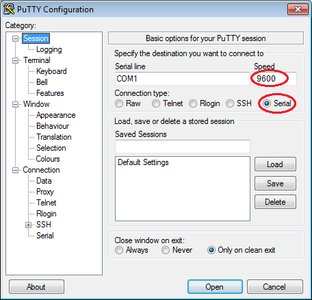
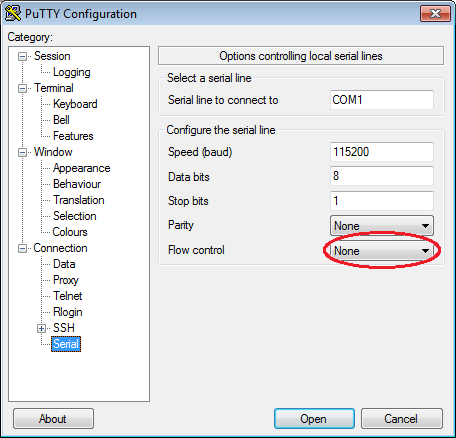
Figure 7. The changes to PuTTY required to listen to the COM0 port (you must match the baud rate defined in your program, in the above case, 9600).
Note: you might try experimenting to see what happens if the baud rates between that defined in your source file and that you entered into the PuTTY configuration. You will find that it doesn't have to be very close, but interesting things happen when you're too far out.
Having opened up the terminal, you can now hit the RESET button on the Keil evaluation board shown in Figure 8.
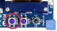
Figure 8. The reset button on the Keil evaluation board.
If you were to execute the above program, download it to the Keil board, and launch PuTTY, then after you hit the reset button, the terminal would print the request for information, prompt you for your name, and then print the statement, as shown in Figure 9.
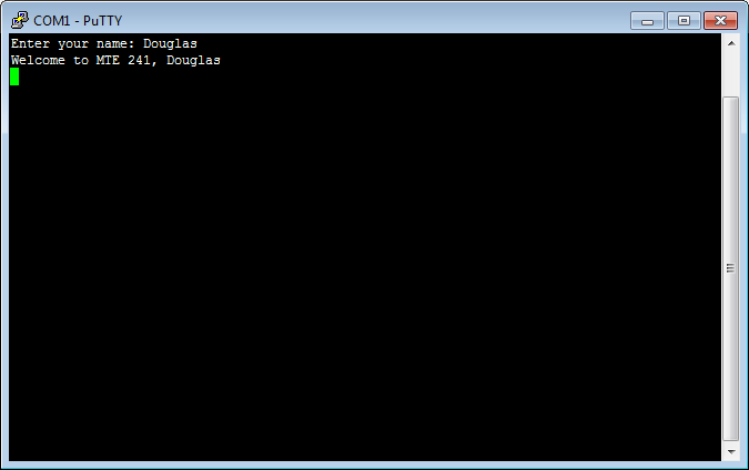
Figure 9. The output on the terminal.
Troubleshooting
If your code does not compile when you include uart.h, check to make sure that your version of system_LPC17xx.c defines SystemCoreClock and not SystemClock. The latter appears to have been defined in previous versions of the μVision IDE. Be sure to use the system_LPC17xx.c the version of μVision4 that is in the laboratory or downloaded from the Keil web site.

Department of Electrical and Computer Engineering
University of Waterloo
200 University Avenue West
Waterloo, Ontario, Canada N2L 3G1
Website maintained by Douglas Wilhelm Harder