main
When you are using a microcontoller, you do not have a system that is initially executing like you do when you execute code on a microprocessor running an operating system. Consequently, there is a little more work that must be done in order to set up the environment.
Let us create a new project, as shown in Figure 1, by selecting Project→New μVision Project.
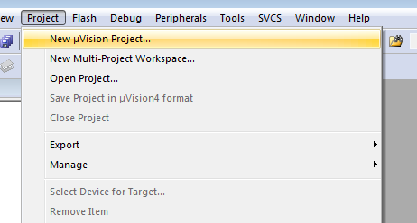
Figure 1. Creating a new project.
I would recommend creating a directory C:\Keil\mte241\, and in this directory, you can create a main directory. Select that directory and give the project a name. In this case, I will start with first_example, as shown in Figure 2.
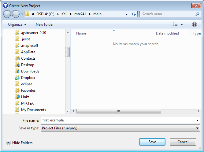
Figure 2. Naming the project.
Finally, you will be asked for the target. Your processor is built by NXP, so if you select that vendor, you will open a list of all the processors made by that vendor. Select the LPC1768, as shown in Figure 3.
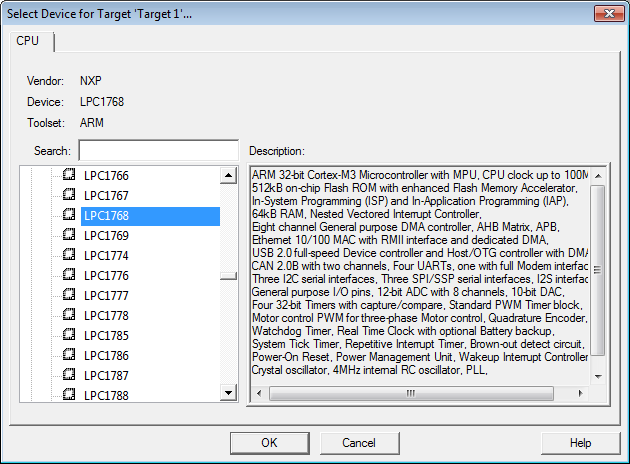
Figure 3. Selecting the device.
You will be asked if you want to Copy 'startup_LPC17xx.s' to Project Folder and Add FIle to Project?'. Select Yes.
Now, open the structure in the Project panel and rename the Source Group 1 to something more descriptive, like Startup code, as shown in Figure 4.
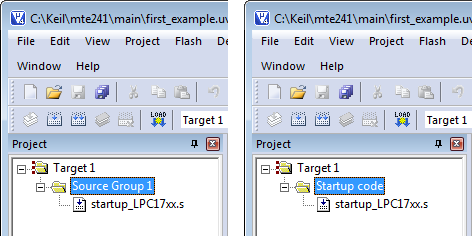
Figure 4. A more resaonable naming convention.
Next, we must create two more groups, so right click on Target and select Add Group... twice. Rename one to Source code and the next to System code.
First, search for the file system_LPC17xx.c within the C:\Keil directory. You should find exactly one instance in the directory C:\Keil\ARM\Startup\NXP\. Copy this file to your project directory C:\Keil\mte241\main\. We must include this file in our project, as it contains the system initialization code. Right click on the System code group and select Add Existing Files to Group 'System code'..., select the file in the browser, select Add, and the select Close.
There are differences between the file system_LPC17xx.c between versions
of μVision. If you are working in the laboratory room, you are using an older version of μVision,
and therefore you must download the system_LPC17xx.c found in that installation.
If you are working both in the laboratory and at home, you may have to change the source file between
working at home and in the laboratory.
Similarly, we must add a file with an executable main() function, so right click on Source code and select Add New Item to Group 'Source code'.... This will open a Add New Item to Group 'Source code' dialog box in which you will select C File (.c) and give it the name main (or whatever else you want to name it).
Now an editor for main.c opens in the next Panel, as shown in Figure 5.
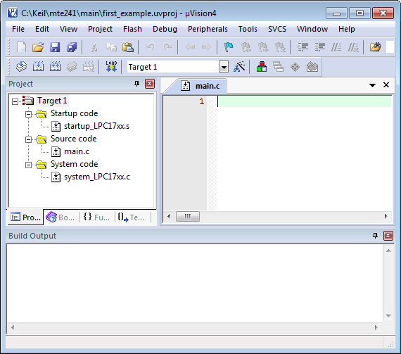
Figure 5. Editing the main.c file.
The library for the board you are using is LPC17xx.h, and each board will have a similar library or libraries to initialize the system. For now, the one function you will require is the SystemInit() function, defined in system_LPC17xx.c. This function initializes the board. Thus, at a bare minimum, we have the following executable:
#include <LPC17xx.h>

int main( void ) {

	SystemInit();

	while ( 1 ) {
		// Do something
	}
}
Because this is an embedded system, we will begin with an infinite loop. Note that it is generally good practice to declare functions with no arguments as taking void. This differentiates C from C++ where you can simply have the declaration int main().
Note that we leave a space between the function signature and the first line. This is a convention in many of the MDK-ARM files, where all variables are declared first followed by a space. If no variables are declared for a function, a space is, never-the-less added after the function signature.
Now you can select Project→Build target from the menu,
F7 on the keyboard, or the icon 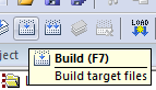 to build
the project. In the Build Output panel, you will see
to build
the project. In the Build Output panel, you will see
Build target 'Target 1'
compiling main.c...
linking...
Program Size: Code=1376 RO-data=236 RW-data=4 ZI-data=612
".\first_example.axf" - 0 Error(s), 0 Warning(s).
You will note one interesting feature at this point: The files main.c and system_LPC17xx.c are now indicated to be expandable, indicated in Figure 6.
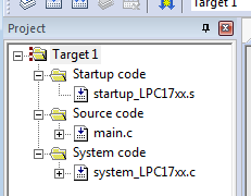
Figure 6. The files main.c and system_LPC17xx.c are now expandable (indicated by a + inside a square).
If we expand these, we see all the files that these depend on, as shown in Figure 7.
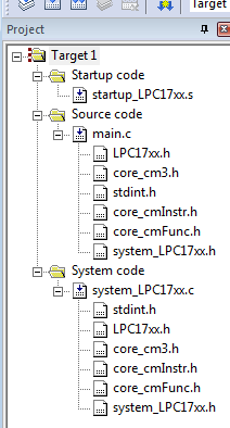
Figure 7. The files main.c and system_LPC17xx.c depend upon.
You can double click on any of these files to examine their contents.
What's next?
Next, learn to use dynamic memory allocation with malloc(...) and free(...) using the MicroLIB.
Optional: A look at SystemInit()
If you look at the file system_LPC17xx.c, you will notice at the very bottom, there is the SystemInit() function, defined as
void SystemInit( void ) {
    /****************
    *  Clock Setup  *
    ****************/
    #if ( CLOCK_SETUP )
        LPC_SC->SCS       = SCS_Val;

        // If the Main Oscillator is enabled, wiat for the oscillator to be ready
        if ( LPC_SC->SCS & (1 << 5) ) {
            while ( (LPC_SC->SCS & (1 << 6)) == 0 );
        }

        // Setup clock divider
        LPC_SC->CCLKCFG   = CCLKCFG_Val;

        /* Periphral clock must be selected before PLL0 enabling and connecting
         * - according errata.lpc1768-16.March.2010 -
         */

        LPC_SC->PCLKSEL0  = PCLKSEL0_Val;     /* Peripheral Clock Selection         */
        LPC_SC->PCLKSEL1  = PCLKSEL1_Val;

        LPC_SC->CLKSRCSEL = CLKSRCSEL_Val;    /* Select Clock Source sysclk / PLL0  */

        #if ( PLL0_SETUP )
            LPC_SC->PLL0CFG   = PLL0CFG_Val;      /* configure PLL0                     */
            LPC_SC->PLL0FEED  = 0xAA;
            LPC_SC->PLL0FEED  = 0x55;

            LPC_SC->PLL0CON   = 0x01;             /* PLL0 Enable                        */
            LPC_SC->PLL0FEED  = 0xAA;
            LPC_SC->PLL0FEED  = 0x55;
            while (!(LPC_SC->PLL0STAT & (1 << 26)));/* Wait for PLOCK0                    */

            LPC_SC->PLL0CON   = 0x03;             /* PLL0 Enable & Connect              */
            LPC_SC->PLL0FEED  = 0xAA;
            LPC_SC->PLL0FEED  = 0x55;
            while ((LPC_SC->PLL0STAT & ((1 << 25) | (1 << 24))) != ((1 << 25) | (1 << 24)));  /* Wait for PLLC0_STAT & PLLE0_STAT */
        #endif

        #if ( PLL1_SETUP )
            LPC_SC->PLL1CFG   = PLL1CFG_Val;
            LPC_SC->PLL1FEED  = 0xAA;
            LPC_SC->PLL1FEED  = 0x55;

            LPC_SC->PLL1CON   = 0x01;             /* PLL1 Enable                        */
            LPC_SC->PLL1FEED  = 0xAA;
            LPC_SC->PLL1FEED  = 0x55;

            // Wait for PLOCK1
            while ( !(LPC_SC->PLL1STAT & (1 << 10)) );

            LPC_SC->PLL1CON   = 0x03;             /* PLL1 Enable & Connect              */
            LPC_SC->PLL1FEED  = 0xAA;
            LPC_SC->PLL1FEED  = 0x55;

            // Wait for PLLC1_STAT and PLLE1_STAT
            //  - note that the bitwise operation works out to 1100000000
            while ( (LPC_SC->PLL1STAT & ((1 << 9) | (1 << 8))) != ((1 << 9) | (1 << 8)) );
        #else
            LPC_SC->USBCLKCFG = USBCLKCFG_Val;    /* Setup USB Clock Divider            */
        #endif

        // Power Control for Peripherals
        LPC_SC->PCONP     = PCONP_Val;

        // Clock output configuration
        LPC_SC->CLKOUTCFG = CLKOUTCFG_Val;
    #endif

    #if ( FLASH_SETUP == 1 )                  /* Flash Accelerator Setup            */
        LPC_SC->FLASHCFG  = (LPC_SC->FLASHCFG & ~0x0000F000) | FLASHCFG_Val;
    #endif
}
Most of this deals with clock setup, followed by a flash accelerator setup. You will note, however, that there is a second tab at the bottom of the file labeled Configuration Wizard, as shown in Figure 8.
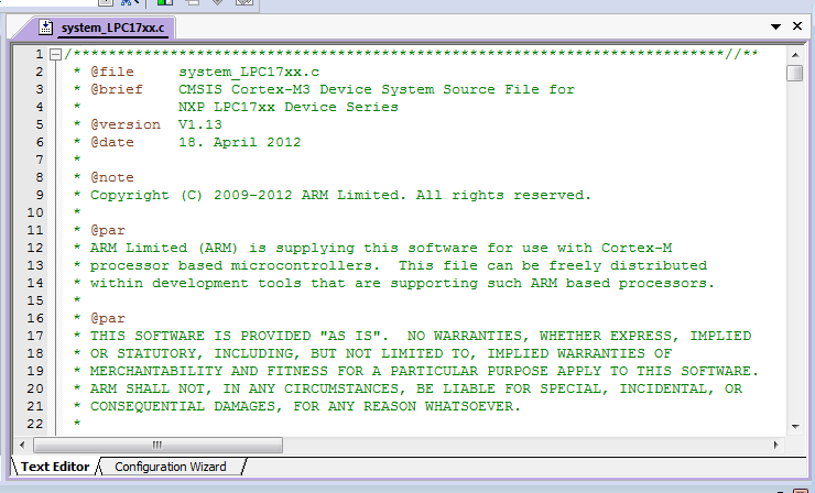
Figure 8. Editing the text file ssytem_LPC17xx.c.
If you select this wizard, you will see a number of parameters that you can modify that specify the settings of the LPC1768. Some of these are shown in Figure 9.
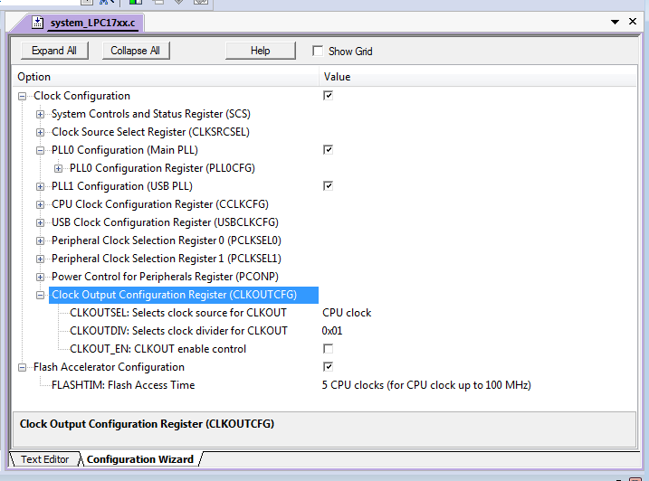
Figure 9. Viewing the configuration wizard of ssytem_LPC17xx.c.

Department of Electrical and Computer Engineering
University of Waterloo
200 University Avenue West
Waterloo, Ontario, Canada N2L 3G1
Website maintained by Douglas Wilhelm Harder