Unified Modeling Language (UML)

Introduction
The Universal Modeling Language (UML) is a language for communicating information about a software system, though it has other business applications, as well. You will not be examined on UML in ECE 250 (except perhaps as a bonus on a quiz), however, we will use one component of UML, namely Class Diagrams, in class to standardize the presentation of information and to introduce you to this industry-standard tool. A good reference is Sinan Si Alhir's Learning UML, published by O'Reilly.
The modeling of systems may be done through functional, object, or dynamic models. The presentation of the models may be described through one or more of thirteen different types of diagrams:
- Structure Diagrams:
- Class Diagrams,
- Component Diagrams,
- Object Diagrams,
- Composite Structure Diagrams,
- Deployment Diagrams, and
- Package Diagrams;
- Behavior Diagrams:
- Activity Diagrams,
- Use-Case Diagrams, and
- State-Machine Diagrams; and
- Interaction Diagrams:
- Sequence Diagrams,
- Communication Diagrams,
- Interaction Overview Diagrams and,
- Timing Diagrams.
Class Diagrams
We will specifically look at Class Diagrams which separate a class into features and associations. The defining features of a class may be broken up into three categories:
- The name,
- Attributes or properties, and
- Operations or behaviours.
The second category may be described through noun phrases, while the third can be describe through verb phrases.
A useful class does not exist in isolation, and therefore must be related to, or associated with, other classes. These associations are defined through lines connecting the various classes, the ornaments (text, arrows, dashed/solid) of the line giving the association.
As an example of a class and how it can be described using a UML Class Diagram, consider a minimum-heap (or min-heap — a data structure which we will see in this class). This data structure requires to keep track of an array and a count. The UML diagram for that class is shown in Figure 1.
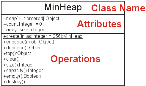
Figure 1. A UML Class Diagram of the MinHeap class.
Attributes
The MinHeap class stores an internal array (heap) capable of storing array_size objects. At any one time, it is holding count objects. These are the attributes or properties of an array. These attributes are recorded in the first box below the name of the class and are expanded upon in Figure 2. For obvious reasons, attributes are also sometimes referred to as properties.
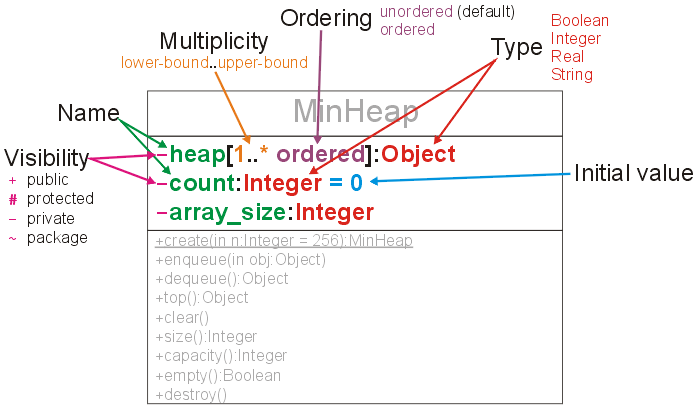
Figure 2. The attributes of the MinHeap class.
To describe the attributes of a class, we include:
- Visibility
- Who is able to access the attributes.
- Name
- The identifier of the attribute.
- Multiplicity
- How many of a particular object are being stored (by default 1, however, a range may be specified where * indicates unbounded).
- Ordering
- Is there an ordering imposed on how the objects are stored (by default, no).
- Type
- The type of the attribute.
- Default Value
- The default value of the attribute.
In the MinHeap class we note that there is:
- A private array heap storing one or more objects is a specified order,
- A private integer count which has an initial value of zero, and
- A private integer array_size.
Operations
At any time that we want to use a heap, we must first construct a new heap (allocate storage and initialize it). Then, because it is a container, we want to perform a number of operations on the heap, including
- Inserting an object into the heap (enqueue),
- Removing an object into the heap (dequeue),
- Determining the top object current in the heap (top),
- Empty the heap (clear),
- Determine the number of objects in the heap (size),
- Determine the maximum number of objects in the heap (capacity), and
- Determine if the heap is empty (empty).
Finally, we may wish to destroy an instance of the MinHeap class.
These all describe various operations we may want to perform on a MinHeap and are summarized in the third box of the class diagram.
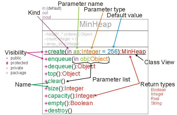
Figure 3. The operations of the MinHeap class.
To describe the operations on a class, we include:
- Visibility
- Who is able to perform the operations.
- Name
- The identifier of the operation.
- Parameter List
- A list of parameters in parentheses, each of which
described by:
- Kind
- Does the parameter bring information into the operation (in), is modified by the operation (out), or both (inout).
- Parameter Name
- The identifier of the parameter.
- Parameter Type
- The type of the parameter (possibly including multiplicity, as shown in Figure 2).
- Default Value
- A default value.
- Return Type
- The type of whatever is returned by the operation.
By convention, the constructor is given the name create while the destructor is destroy.
If an attribute or operation is underlined, this indicates that the feature has class scope, that is, the feature is shared by all instances of that class. Such an operation or attribute can be accessed.
In the MinHeap class we note that there is:
- A public constructor which takes an integer as an argument which has a default value of 256 and returns an instance of the MinHeap class.
- A public operation enqueue which takes an argument of type Object (which should not be modified by the operation).
- A public operation dequeue which returns an object.
- A public operation top which returns an object.
- A public operation clear.
- Public operations size and capacity which return integers.
- A public operation empty which returns true or false.
- A public destructor which removes the class.
Example 1
The Class Diagram for Project 1 is shown in Figure 5. You can then compare this with the C++ template for the corresponding implementation. You will note that I have tried to highlight the related features.
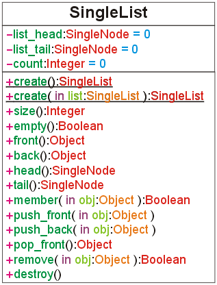
Figure 5. The UML Class Diagram for the class SingleList for Project 1.
You may notice that there are some features in UML which cannot be directly translated to C++ and vice versa. For example, you cannot declare a parameter to be of Kind out, that is, the variable can be modified but not accessed. In C++, you can declare that a function cannot modify the object it is being called upon by placing const after the parameter list, e.g., int size() const. This cannot be shown in a UML Class Diagram. You may also note that, with the exception of initial values (which affect the constructors), nothing in the Class Diagram describes anything inside the body of the operations. The Class Diagram describes what the operations (functions) do, not how they work.
Example 2
The UML Class Diagram for a Rational class is shown in Figure 6. In this class, there is the class operation gcd. This would suggest that such a function does not really belong in the Rational class, and thus, if time permitted, such a function may be implemented in a more appropriate location and the Rational class would then only call the gcd operation.
Other class-scope operations are the binary operators +, -, *, and /; and the unary operator -. The named operations, add(q), subtract(q), etc., would affect the object itself.
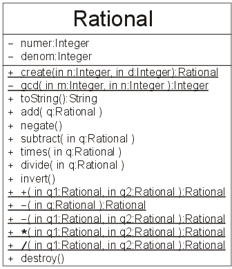
Figure 6. The UML Class Diagram for the class Rational from ECE 150.
Associations
As well as showing the features of individual classes, it is also useful to discuss the relationships between various classes.
Two associations we will look at are inheritance (subclasses or is a) and containment (has a).
The notion of inheritance (subclasses, derived classes, etc.) is well represented by the relationship is a. As an example of inheritance, consider developing a graphics program such as CorelDraw or Illustrator. In such a package, each shape on the screen is represented by a separate object.
To give a illustration, consider Figure 7 which is comprised of rectangles and circles, each with various sizes, shapes, and colours. Each shape has a border as well as an interior, and the border colour may be different from the interior colour.
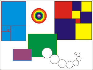
Figure 7. An illustration using circles and rectangles.
While this may appear to be a trivial example, consider that all the graphics in the ECE 250, ECE 204, and ECE Undergraduate pages as well as most of the graphics in the ECE 250 slides are created using CorelDraw, each graphic being a collection of overlapping shapes.
Thus, as the graphic is a collection of shapes, it is the responsibility of the graphic to maintain a collection of shapes and their relative orderings on the screen, for example, the rainbow has a white circle on top of a purple circle, which is on top of a blue circle, etc. Thus, the application must have a general Shape class, from which all other shapes are derived. In this toy example, we will consider two sub-classes: Circle and Rectangle.
Every graphic object has a border and an interior, and each may have a different colour. Thus, the general Shape class contains (has) two attributes storing these colours. To properly deal with colours, we must also have a Color class. In this case, the Color class is defined using red-green-blue (RGB), however there are methods for getting the appropriate colours for cyan-magenta-yellow (CMY) and cyan-magenta-yellow-black (CMYK) which are used for printing. There are also appropriate operations to change the colour of both of these shapes.
The two sub-classes Circle and Rectangle must have location information, an thus, this is stored using another class, a two-dimensional Point class which stores a coordinate (x, y). In addition to the operations in the Shape class, these two classes have additional operations which are relevant to the shapes which they represent.
The associations between all of these five these classes is shown in Figure 8.
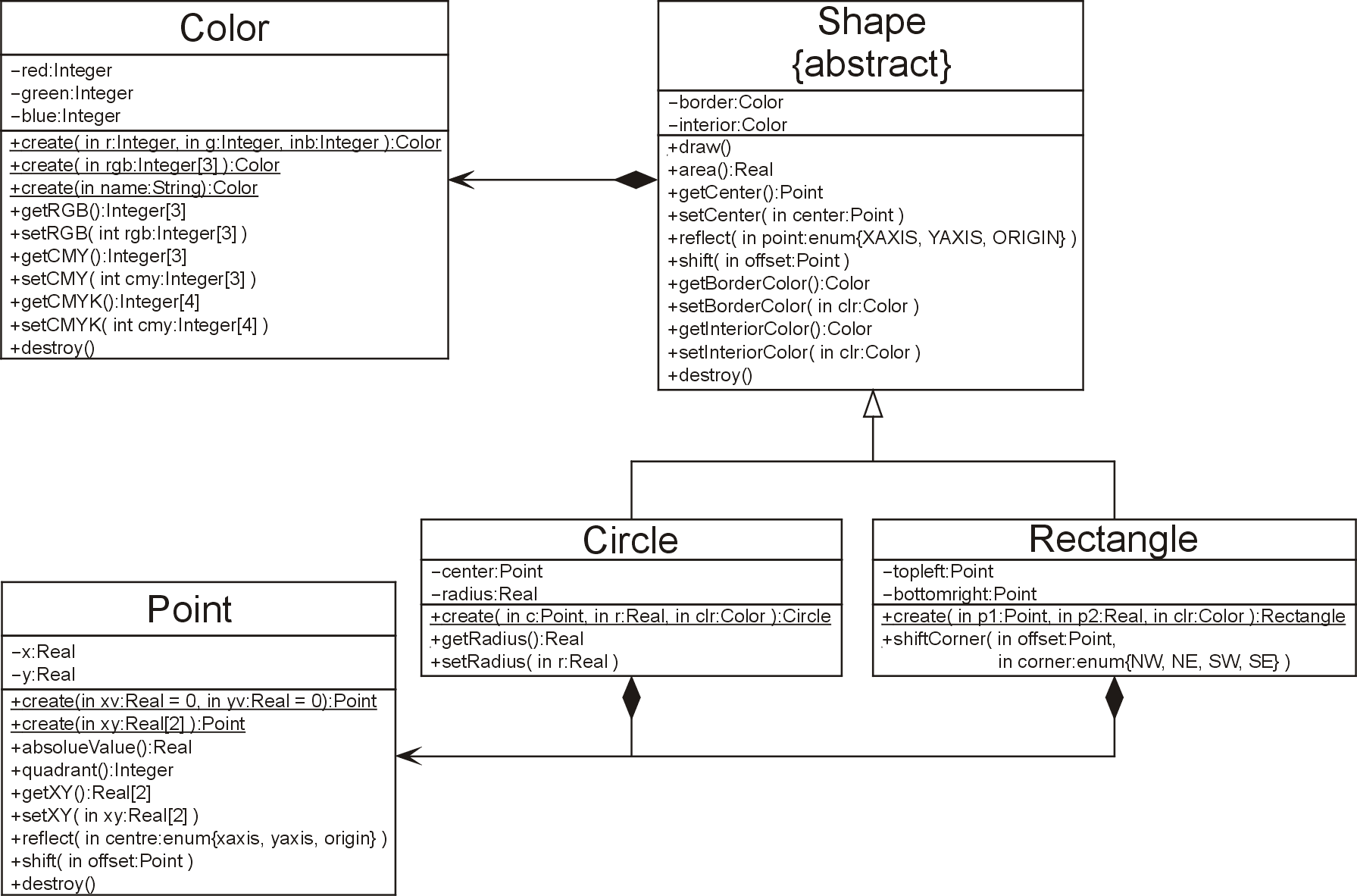
Figure 8. The association between the Color, Point, Shape, Circle, and Rectangle classes (click to enlarge).
Because every Circle is a Shape, and every Rectangle is a, we use inheritance. Alternatively, every Shape has two colours (border and interior), every Circle has a centre, and every Rectangle has two points which define the corners, and thus, we use containment. Thus, the association used in the first case (inheritance) is shown with an open arrow, while in the second case (containment) is shown with an arrow-head backed by a diamond.
Students who go on to learn UML in greater detail will learn the significance of other features for associations in UML Class Diagrams, however, what has been covered here is sufficient for this course.
Comment on Spellings
Note the (unfortunate) use of American spelling. One consequence of having the largest market being 300 million individuals who cannot spell correctly is that it is, no matter how distasteful, necessary to use spellings which are appropriate to them. You may grumble and complain, but ultimately, when you implement any code, unless there is a firm policy otherwise, use American spellings, e.g., center and color.
C++ Code
C code, C code run, run code run.
The images shown in Figures 1 through 3 use the generic UML terms for various types. It is not uncommon to use language-specific types for the description of a class which is to be implemented in a particular programming language. For example, Figure 4 shows Figure 1 tailored to C++ naming conventions.
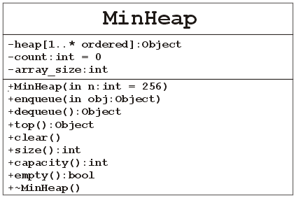
Figure 4. A C++ variation of the MinHeap class.
The most obvious difference is the representation of constructors and destructors. By convention the create operation has class scope. In C++, however, the implementation of classes uses a constructor which is an operation called on an object created by the new operator. Consequently, the constructor does not have class scope.
UML Class Diagrams and C++ Function Signatures
There is a strong relationship between the declaration of a variable in a C++ class and the description of an attribute in a UML Class Diagram. For example, the attribute
	-count:Integer = 0
	-heap[1..*]:Object
could be implemented as a class member
	private:
		int count;
		Object * heap;
however, the initialization would appear in the constructor.
There is a similar association between the signature of a C++ member function and the description of an operation in a UML Class Diagram. For example, the operations
	+enqueue( in obj:Object )
	+dequeue():Object
	+size():Integer
	+empty():Boolean
would be interpreted as the signatures
	public:
		void enqueue( Object obj );
		Object dequeue();
		int size();
		bool empty();
respectively. In C++, to declare that a function does not return something, the return type must be stated to be void.
A constructor such as
+create( in re:Real = 0, in im:Real = 0 )
in a complex class could be interpreted as
	public:
		Complex( double re = 0.0, double im = 0.0 );
In C++, because the constructor is required to create an instance of the given class, there is no need for a return type.
Summary
UML is a collection of standardized practices for describing software systems, though it can be used in other situations as well. Specifically, we are looking at Class Diagrams which are useful for succinctly describing the features of a class, describing the features (attributes and operations) and associations with other classes. While we may not know the implementation of a particular class (for example, the MinHeap class), the Class Diagram gives an overview of what is being stored and how we can access and use the class.
Questions
1. Given the UML Class Diagram
| SortedArray |
|---|
| +create():SortedArray +create( v:SortedArray ):SortedArray +binary_search( n:int ):Boolean +insert( n:int ) +remove( n:int ):Boolean |
create the definition of a class.
2. Given the UML Class Diagram
| Quaternion |
|---|
| -r:Real -i:Real -j:Real -k:Real |
| +create( in re:Real = 0.0, in im:Real = 0.0, in jm:Real = 0.0, in km:Real = 0.0 ):Quaternion +create( in q:Quaternion ):Quaternion +abs():Real +conj() +negate() +add( in q:Quaternion ):Quaternion +multiply( in q:Quaternion ):Quaternion +sin():Quaternion +cos():Quaternion +tan():Quaternion +real():Real +imag():Quaternion +is_real():Boolean +is_imaginary():Boolean |
create the definition of a class.
3. Given the C++ class header
class Coordinate {
	private:
		double x, y;

	public:
		Coordinate( const double xp = 0.0, const double yp = 0.0 );
		Coordinate( const Coordinate & coord );

		double getX() const;
		double getY() const;
		void setX( const double xp );
		void setY( const double yp );

		double length() const;
		double angle() const;
		double distance( const Coordinate & coord ) const;

		void transform( const Transformation & T );
};
create the corresponding Class Diagram.
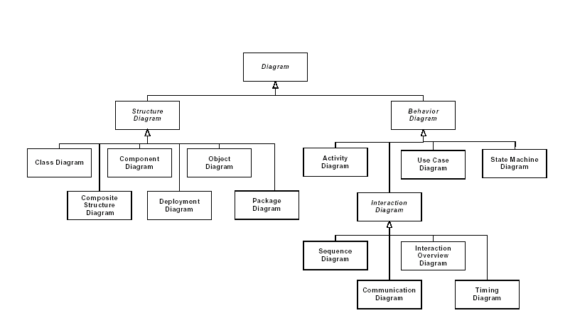
4. At the top of this page are listed fourteen different diagram classes. Use the following sentences to draw an appropriate Class Diagram of UML Diagrams. Start with a single class called Diagram.
- Structure and Behaviour Diagrams are Diagrams.
- Class, Component, Object, Composite Structure, Deployment, and Package Diagrams are Structure Diagrams.
- Activity, Use Case, State Machine, and Interaction Diagrams are Behaviour Diagrams.
- Sequence, Interaction Overview, Communication, and Timing Diagrams are Interaction Diagrams.
Answer (Reference: Wikipedia).
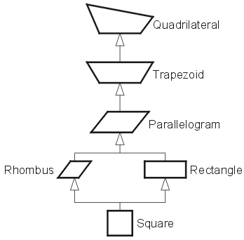
5. Draw an appropriate class diagram for the following shapes:
- Rectangle
- Trapezoid
- Square
- Rhombus
- Quadrilateral
- Parallelogram
Acknowledgments
The author would like to thank Hanan Ayad and Sharon Swan for their input into this topic.

Department of Electrical and Computer Engineering
University of Waterloo
200 University Avenue West
Waterloo, Ontario, Canada N2L 3G1
Website maintained by Douglas Wilhelm Harder