Simulations
What is a simulator and how does it work?
As we have seen in class, a computer is nothing more than registers that are operated on by instructions. Consequently, it should be possible to simulate a computer. For example, if you ever want to experience what it is like to play a video game on the Atari 2600 VCS, you can go to the site stella.sourceforge.net and download an emulator. Basically, this system will interpret each command, and the state of the processor can be simulated through a data structure such as:
	#define NEGATIVE    (1 << 7)
	#define OVERFLOW    (1 << 6)
	#define BREAKPOINT  (1 << 4)
	#define BCD         (1 << 3)  // Binary-coded decimal
	#define INTERRUPT   (1 << 2)
	#define ZERO        (1 << 1)
	#define CARRY       (1 << 0)

	typedef struct {
		unsigned char A;     //  8 bits  Accumulator
		unsigned char X;     //  8 bits  Index register for offsets of addresses
		unsigned char Y;     //  8 bits  Index register
		unsigned char SP;    //  8 bits  Index register
		unsigned short PC;   // 16 bits  Program counter
		unsigned char SR;    //  8 bits  Status register:   NV-BDIZC
	} MOS6507_t system;  // Here, system is a global variable of this unnamed structure
Instructions (themselves binary machine instructions) are parsed and the register values are modified as appropriate. It is likely that RAM would be simulated with an array of size 128 bytes, and the cartridges could store at most 4 KiB of ROM, an array of size 4096.
	unsigned char Atari2600_RAM[128];
	unsigned char Atari2600_ROM[4096];
Now, to start executing, the program counter is set to 0 and the instruction at
	system.PC = 0;

	while( 1 ) {
		interpret_instruction( Atari2600_ROM[system.PC], &system );
	}
As system is being sent, the byte containing the instruction need not even be sent, but this is to demonstrate what is being done. Each of the instructions at 6502 op codes would have to be interpreted.
The purpose of this introduction is to demonstrate a relatively simple system and how one could simulate it.
Simulations of the Keil board
In Project 1, you were using the LCD screen, and this output cannot be simulated in μVision. Other devices, however, can be simulated, and the output will be redirected as if it was coming from the board. Most useful is the universal asynchronous receiver/transmitter (or UART). We will assume for the balance of this program that you are writing a program that prints Hello world! to the UART.
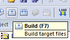
To simulate a program executing on the Keil board, you must first build the project by
- F7
- Select Project→Build Target
- Select the icon
The output of the compiler will appear in the Build Output. If you are successful, the output will be something like:
Build target 'LPC1768'
compiling uart_polling.c...
linking...
Program Size: Code=1180 RO-data=236 RW-data=4 ZI-data=612
".\Hello_world.axf" - 0 Errors, 0 Warning(s).
If this is not the case, it will list the errors. Each error line will begin with the file where the error apparently occurs, for example
src\main.c(8): error: ...
This example indicates the error is on line 8 and double clicking on the error message will bring you to line 8 in main.c.
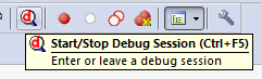
Once you have a successful build, to simulate the execution of this program on the Keil evaluation board, we will use the debugger. To start or stop the debugger, you have three options:
- Ctrl-F5
- Select Debug→Start/Stop Debug Session
- Select the icon
When you do so, a dialog box may appear with the text EVALUATION MODE Running with Code Size Limit: 32K. This indicates that you are using a version of μVision which does not have a full licence; consequently, there are some restrictions including the restriction that the code cannot be larger than 32 KiB—something that should not be an issue for MTE 241. Just select OK.
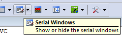
Having started the debug mode, we need to view the output of the UART. To do so, you have two options:
- Select View→Serial Windows→UART #1
- Select the icon
Note the ambiguity: COM0 is listened to by UART #1. You will note that UART #1 is one of the panels of the lower right window in μVision.
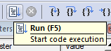
To run the code, you have three options:
- F5
- Select Debug→Run
- Select the icon
Having done so, you should see
Hello world!
appear in the UART #1 panel.
Note: because there is an infinite loop coded into the Hello world program, you can terminate the execution through one of two options:
- Select Debug→Stop
- Select the icon
Before you run it again, you should reset the microcontroller through one of two options:
- Select Debug→Reset
- Select the icon style="vertical-align:middle"
Later, we will discuss some of the other features of the debugger.

Department of Electrical and Computer Engineering
University of Waterloo
200 University Avenue West
Waterloo, Ontario, Canada N2L 3G1
Website maintained by Douglas Wilhelm Harder